RF & Wireless Systems · Hardware
Wireless Well-Tank Control System
No cable needed between pump and tank.
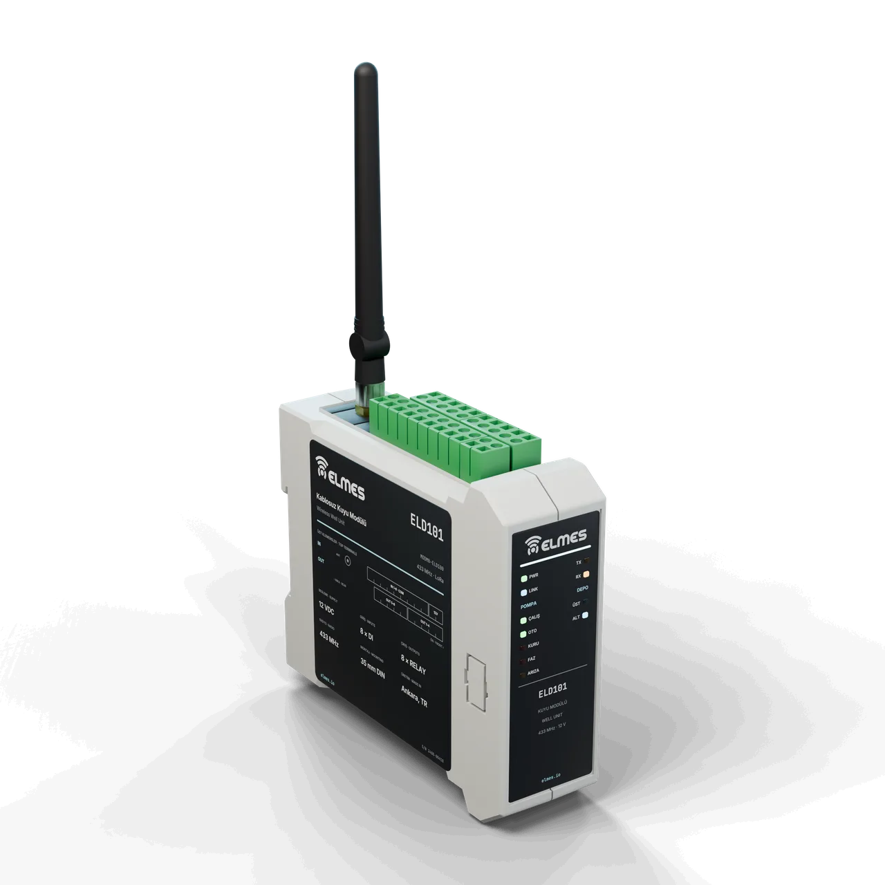
Overview
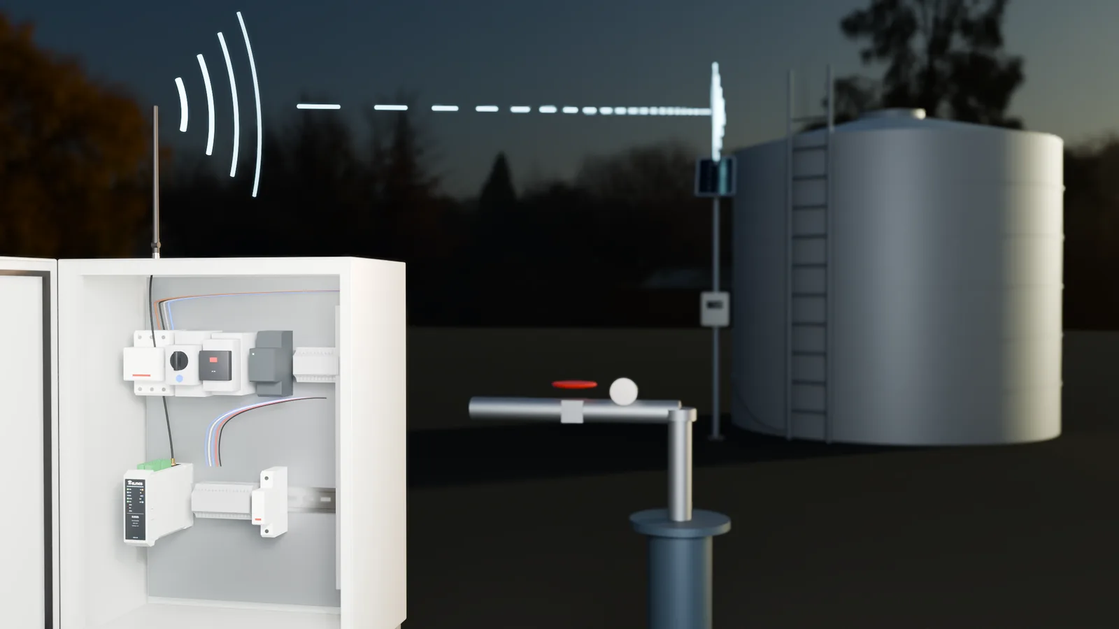
The problem in the field. There are often hundreds of meters to kilometers between a well/pump and the water tank. Carrying level information by cable means trenching, cable theft and lightning damage. In manual operation, the tank overflows (wasting water and energy) or runs dry (supply interruption); the pump runs dry and burns out, and phase faults damage the motor.
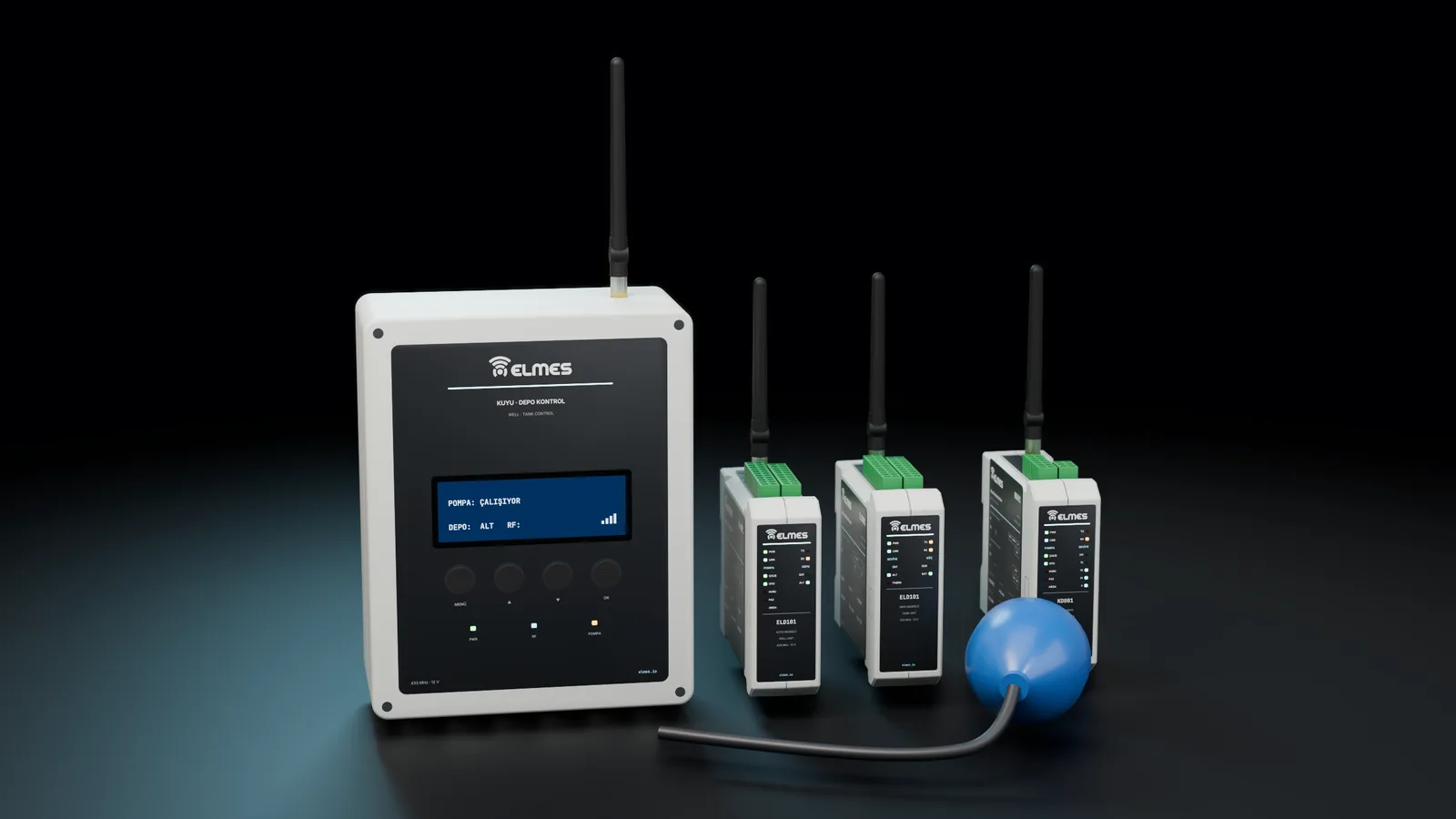
The solution. The tank unit reads the level from a float switch or an analog level sensor and sends it wirelessly to the well unit. The well unit starts the pump at the low level and stops it at the high level, protecting it through dry-run and phase-protection inputs. If communication is lost, the pump stops after a defined time. Status is visible on site via LCD/LED, and several tanks and wells are managed in the same system. Tanks without mains power use a solar panel kit. The first generation (N1) and the ELD100-based second generation (N2) are in the field; the new KD001 board is coming soon.
Expansion. The roadmap covers level/flow telemetry with an analog level sensor (4–20 mA) and a flow meter (shared with the Wireless Analog & Digital Data Link), SCADA and mobile monitoring through the Wireless Gateway / RTU and Telemetry & Process Intelligence, and a water-network loss and leak package. For general-purpose contact transfer, the same platform is offered as the Wireless Digital I/O Link.
Features
- Dry-run protection: when dry running is detected via an electrode or current input, the pump stops and an alarm is raised.
- Phase protection: start inhibit via a phase-sequence / phase-loss relay input.
- Float filter: prevents false triggering caused by fluctuating levels (ELD100).
- Multiple tanks / wells: several tanks and wells in the same system.
- Repeater: range extension with a relay station on long or obstructed paths.
- Solar-powered tank unit: for tanks without mains power.
- Safe stop on link loss: the pump stops within a defined time.
- Local display: LCD (N1) / LED (N2).
- Handheld module: manual pump control.
- General-purpose derivatives: on/off and pump control derivatives are covered by the Wireless Digital I/O Link.
- TargetAutomatic retry: adjustable retry time after a dry-run stop.
- TargetPriority and sequencing logic: pump priority and sequenced operation across multiple wells/tanks.
- TargetLevel + flow telemetry: analog level (4–20 mA) and flow meter; a telemetry node shared with the Wireless Analog & Digital Data Link.
- TargetEnhanced local display: level, link and alarm indication.
- TargetSCADA / mobile monitoring: through the Wireless Gateway / RTU and Telemetry & Process Intelligence; Modbus RTU/TCP.
- TargetNew-series hardware: the KD001 board, an EM-module-based repeater and a handheld remote based on the Wireless Call Button Platform.
Generations
| Model code | Generation | Highlights | Status | Request a quote |
|---|---|---|---|---|
| — | N1 (first generation) | LCD display; repeater (relay station) | In the field | Request a quote: N1 (first generation) |
| MODM0-ELD100 | N2 (ELD100) | LoRa; LED display; float filter | In the field | Request a quote: MODM0-ELD100 |
| KD001-P1Target | New board (KD001) | Next-generation well-tank board | Coming soon | Request a quote: KD001-P1 |
Specifications
Values marked “Target” are design targets, next-generation values or chip-vendor data; they are updated as measurement and certification are completed.
| Generations in the field | N1 and N2 (ELD100) |
|---|---|
| New board | KD001Target |
| Pump logic | Start at low level, stop at high level |
| Level sensing | Float switch or analog level sensor |
| Protection inputs | Dry run (electrode / current), phase sequence / phase loss |
| On link loss | The pump stops after a defined time |
| Local display | LCD (N1) / LED (N2) |
| Tank unit power | Solar panel kit option |
| Frequency band | 433.05–434.79 MHz, 8 channels; 868 MHz as an optionTarget |
|---|---|
| Output power | +22 dBmTarget |
| Receiver sensitivity | −129 dBm @ SF11 (chip datasheet)Target |
| Modulation | LoRa SF9–SF12Target |
| Antenna | SMA (EC carrier board)Target |
| Open field | ≥ 2000 m (SF11, 2 m height)Target |
|---|---|
| Obstructed terrain | ≥ 500 m; with repeatersTarget |
| Encryption | AES-128-CCMTarget |
|---|---|
| Addressing | 16-bit network ID + 16-bit addressTarget |
| Systems on the same site | ≥ 8 networksTarget |
| Level-to-pump latency | ≤ 2 sTarget |
|---|---|
| Pump stop on link loss | 1–30 min, adjustableTarget |
| Float filter | 1–60 s, adjustableTarget |
| Watchdog | Independent hardware watchdog (IWDG)Target |
| Supply | 9–36 VDC; 230 VAC adapter; 10–20 W solar panel + batteryTarget |
|---|---|
| Consumption | < 1 W in standbyTarget |
| Digital inputs | 8 × 12–24 V (EC-DIO8)Target |
|---|---|
| Relay outputs | 8 × 5 A / 250 VAC (EC-DIO8)Target |
| Analog inputs | EC-AIO: 4 × 16-bitTarget |
| Pulse input (flow) | EC-PLSTarget |
| Communication | RS485 / Modbus (EC-485); gateway connectionTarget |
| Enclosure | DIN housing + IP65 field enclosureTarget |
|---|---|
| Display (new series) | LED status indicators; LCD optionTarget |
| Operating temperature | −25…+70 °CTarget |
| Humidity | Up to 95 %, non-condensingTarget |
| Warranty | 2 years; manufacturing and service in Ankara |
|---|
Applications
- Municipal and village drinking-water networks
- Water utilities
- Industrial water supply (cement, sugar, chemicals)
- Farm and greenhouse water tanks
- Public campuses
- Residential booster pump systems
- Irrigation tanks
In an existing pump panel, the relay output connects to the contactor coil and the phase-protection and dry-run signals connect to the inputs; the manual/automatic switch is retained. In irrigation tanks, it works together with the Wireless Irrigation Control System: tank level and pump protection are coordinated with the irrigation program.
For applications that carry only a few contacts without level logic (remote start/stop, fault signal), the Wireless Digital I/O Link can be used.
Compliance & documentation
There is no product-level CE declaration of conformity or RED test report yet; documentation is being prepared according to the plan below.
- TargetCE – RED 2014/53/EU (EN 300 220-2, EN 301 489-1/-3)Starting at module level
- TargetLVD / EN 61010-1 — pump panel connection
- TargetRoHS declaration
- TargetCE declaration of conformity, user manual and wiring diagram
References
Some of the organizations using this product family.
- İSKİ
- Atom Enerji Kurumu (TAEK)
- Rize Pazar Belediyesi
- Şeker Fabrikaları A.Ş.
- Sançim Bilecik Çimento
- Gemi Kaya Holding
- Adel Elektrik Otomasyon
Frequently asked questions
Will several well-tank systems in the same area interfere?
No. Every system has its own ID; packets with a different ID are ignored. The new series targets at least 8 independent networks through channel × network-ID combinations.
What does the pump do if communication is lost?
If the well unit receives no level data within the defined time, it stops the pump and shows “no link”, preventing overflow and dry running.
There is no power at the tank; will it work?
Yes, the tank unit runs on a solar panel + battery kit.
Can it be connected to an existing pump panel?
Yes. The relay output connects to the contactor coil and the phase-protection and dry-run signals connect to the inputs; the manual/automatic switch is retained.
How can the range be extended?
Antenna height, directional antennas (Industrial RF Antenna Series) and repeaters; on obstructed terrain, the repeater is placed on a high point.
Can several tanks or wells be connected?
Yes; the number of units in a system can be increased. Advanced priority and sequencing logic for multiple wells/tanks is planned in the new series.
Can data reach a SCADA system or a phone?
The current generation offers a local display and a dry-contact output. Modbus/SCADA through the Wireless Gateway / RTU and mobile monitoring through Telemetry & Process Intelligence are planned.
How is it different from the Wireless Digital I/O Link?
The well-tank system is an application product with level, pump-protection and link-loss logic built in. The Wireless Digital I/O Link uses the same platform for general-purpose contact transfer.
What about warranty and service?
2-year warranty; manufacturing and service in Ankara; spare units from stock.
Get a quote for this product
Our engineering team replies within 24 hours.
Related products
 RF & Wireless Systems
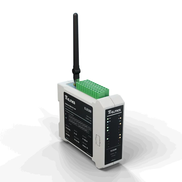
Wireless Digital I/O Link — 8 Channels
8 relays, 8 inputs — replace the cable with RF.
View details: Wireless Digital I/O Link — 8 Channels RF & Wireless Systems
Wireless Analog & Digital Data Link
Carry 4–20 mA / 0–10 V signals wirelessly.
View details: Wireless Analog & Digital Data Link Coming soonModules, Boards & Gateways
Wireless Gateway / RTU
Connect every LoRa node in the field to SCADA, the cloud and PLCs with a single box.
View details: Wireless Gateway / RTU