RF & Wireless Systems · Hardware
Wireless Analog & Digital Data Link
Carry 4–20 mA / 0–10 V signals wirelessly.
Overview
The problem in the field. Between a field sensor (level, pressure, flow, temperature) and the control room there may be a road, a river, a railway, another company's property or simply several hundred meters. Running cable means trenching, permits and theft; the longer a 4–20 mA line gets, the more noise and grounding problems it picks up. Collecting multi-point contact signals (motor status, doors, level switches) one cable at a time is expensive.
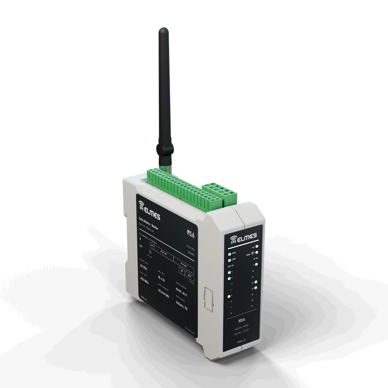
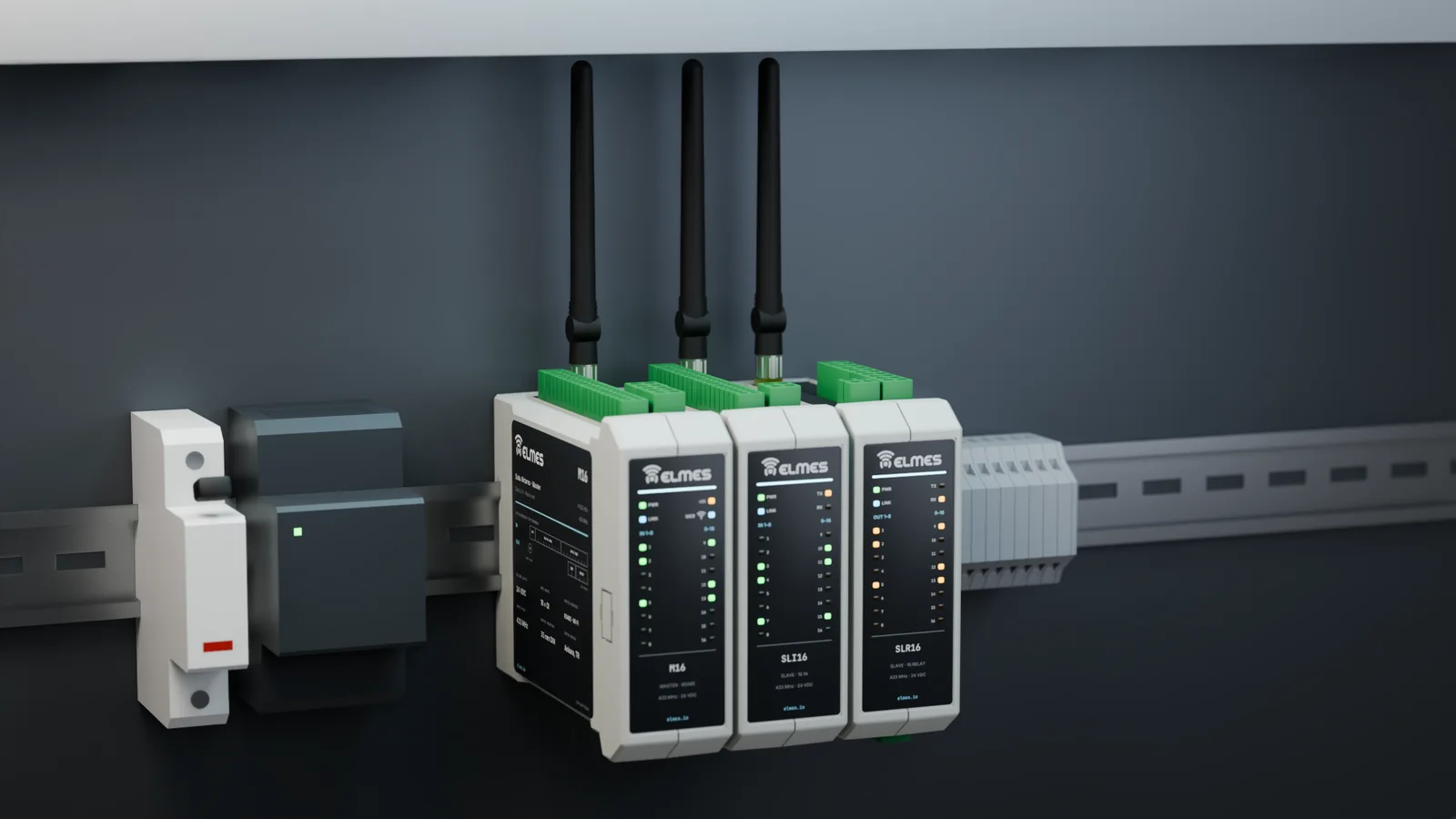
The solution. The data link digitizes the digital inputs and analog signals at one end and carries them over 433 MHz to the other end, where relay and analog outputs hand them to the PLC "as if hard-wired". The M16 master unit of the RT152 family collects 16 inputs, talks to the PLC over RS485 / Modbus RTU and is monitored through a web interface; SLI16 input and SLR16 relay expansion units increase the channel count. If the link drops, the outputs go to a defined safe state and a fault contact is signaled.
Expansion. The new series targets a battery-powered telemetry node (powering a level/flow/pressure sensor from a battery or solar panel and reporting periodically) and a pulse (meter) input (wireless reading of water/electricity meters through their S0 pulse output, sharing its platform with the Wireless Meter Reading Node). Modbus TCP via the Wireless Gateway / RTU, cloud monitoring via Telemetry & Process Intelligence and use as a building block of the IIoT Retrofit Kit are planned.
Features
- Transparent I/O: an input contact appears as a relay at the far end; to the PLC it behaves like a cable.
- One-to-one analog transfer: 0/4–20 mA, 0–10 V, potentiometer, joystick (analog/digital); the same platform as the analog speed transfer in crane and machine remotes.
- Master + expansion architecture: M16 master with SLI16 input and SLR16 relay expansion units.
- RS485 / Modbus RTU: channel states and analog values are passed to the PLC as registers.
- Web interface (M16): channel status, RSSI and configuration from a browser.
- Link monitoring: heartbeat packets, link-fault relay and LED, defined safe state.
- Optional modules: directional antenna and IP65 field enclosure.
- TargetAdjustable safe state: the timeout and output state on link loss are user-configurable.
- TargetModbus TCP and cloud: Modbus TCP through the Wireless Gateway / RTU, cloud monitoring through Telemetry & Process Intelligence.
- TargetTelemetry node: battery or solar powered; periodic reports from a level, flow or pressure sensor with battery and RSSI data; shared with the well and reservoir system.
- TargetPulse (meter) input: S0 water/electricity meter reading and production counting; the same EC-PLS board as the meter reading node.
- TargetRepeater: range extension with the same hardware.
- TargetIIoT Retrofit Kit building block: connecting legacy machine fleets without tearing anything out.
RT152 family
| Model code | Unit | Contents | Status | Request a quote |
|---|---|---|---|---|
| M16 | Master unit | 16 inputs; RS485 / Modbus RTU; web interface (channel status, RSSI, configuration) | In the field | Request a quote: M16 |
| SLI16 | Input expansion | Additional input channels for the master | In the field | Request a quote: SLI16 |
| SLR16 | Relay expansion | 16 relay outputs | In the field | Request a quote: SLR16 |
| —Target | Telemetry node | Battery or solar powered; level, flow or pressure sensor; periodic reports with battery and RSSI data | Planned | Request a quote: Telemetry node |
| —Target | Pulse-input version | 4× S0/reed meter inputs; shared with the meter reading node | Planned | Request a quote: Pulse-input version |
Specifications
Values marked “Target” are design targets, next-generation values or chip-vendor data; they are updated as measurement and certification are completed.
| Family | M16 master + SLI16 input and SLR16 relay expansion units |
|---|---|
| Frequency | 433 MHz |
| Digital channels | 16 digital inputs + 16 relays; more with expansion units |
| Analog channels | 8 analog outputs; 4–22 mA analog input |
| Analog signal types | 0/4–20 mA, 0–10 V, potentiometer, joystick |
| PLC interface | Relay contacts, analog outputs, RS485 / Modbus RTU |
| Web interface | Channel status, RSSI and configuration (M16) |
| On link loss | Outputs go to a defined safe state; link-fault contact and LED |
| Frequency band | 433.05–434.79 MHz, 8 channels; 868 MHz as an optionTarget |
|---|---|
| Output power | +22 dBmTarget |
| Receiver sensitivity | −129 dBm @ SF11Target |
| Modulation | LoRa SF7–SF10 (low SF for faster analog updates)Target |
| Data rate | ~5.5 kbps at SF7Target |
| Antenna connector | SMA (EC carrier board)Target |
| Open field | ≥ 2000 m (SF9, 2 m height)Target |
|---|---|
| Industrial environment | ≥ 300 mTarget |
| Encryption | AES-128-CCMTarget |
|---|---|
| Addressing | 16-bit network ID (NetID) + 16-bit addressTarget |
| Systems on the same site | ≥ 8 independent networksTarget |
| Digital input → relay | ≤ 100 ms (SF7)Target |
|---|---|
| Analog update rate | 100 ms–10 s, adjustableTarget |
| Fail-safe on link loss | 1–60 s, adjustableTarget |
| Watchdog | Independent hardware watchdog (IWDG)Target |
| Supply | 9–36 VDC; 230 VAC adapterTarget |
|---|---|
| Consumption | Depends on the number of relays |
| Standby consumption | < 2 WTarget |
| Battery node | Based on EM-G0L-433-LP; sleep < 10 µA; ≥ 3 years at 15-minute reportingTarget |
| Digital inputs | 16 opto-isolated inputs, 12–24 V (EC-DIO16)Target |
|---|---|
| Relay outputs | 16 relays 5 A / 250 VAC or transistor outputs (EC-DIO16)Target |
| Analog inputs | 4× 4–20 mA / 0–10 V, 16-bit (EC-AIO)Target |
| Analog outputs | 2× 4–20 mA / 0–10 V, 12-bit DAC (EC-AIO)Target |
| Pulse inputs | 4× S0/reed, ≤ 10 kHz (EC-PLS)Target |
| Serial communication | Isolated RS485, Modbus RTU (EC-485); Modbus TCP through the Wireless Gateway / RTUTarget |
|---|---|
| Wi-Fi / web | Configuration over web and BLE via ESP32 (EM-G0LW)Target |
| Enclosure | DIN-rail housing, 6–9 modulesTarget |
|---|---|
| Mounting | 35 mm DIN railTarget |
| Operating temperature | −25…+70 °CTarget |
| Humidity | Up to 95 %, non-condensingTarget |
| Warranty | 2 years; manufacturing and service in Ankara |
|---|
Applications
- Water and wastewater plants
- Well and reservoir sites
- Mines and quarries
- Cement and chemical plants
- Glass / porcelain kiln lines
- Machine-to-panel analog control
- Crane / machine receiver side
- Energy and infrastructure sites
- Legacy machine fleets (retrofit)
The ready-made system for well and reservoir applications is described on the Wireless Well & Reservoir Control System page. Analog speed transfer in crane and machine remotes uses the same platform as the Wireless Crane Control System and Wireless Machine Start & Control.
Target applications: level/flow/pressure telemetry and leak/loss monitoring in water networks (with Telemetry & Process Intelligence).
Fuel tank sites: tank farms are ATEX/Ex zones and the current hardware has no Ex certification. This application is only considered case by case, with Ex-certified sensors and installation outside the zone or in a certified enclosure.
Compliance & documentation
There is no CE declaration of conformity or RED test report for the RT152 family yet. Product documentation is being prepared according to the plan below, starting at module level.
- TargetCE – RED 2014/53/EU (EN 300 220-2, EN 301 489-1/-3)Starting at module level
- TargetEMC – EN 61326-1 / EN 61000-6-2 / EN 61000-6-4
- TargetLVD – EN 61010-1Version with 230 VAC adapter
- TargetRoHS declaration
- Out of scopeATEX / ExFuel tank sites are assessed separately, case by case
- TargetCE declaration of conformity, user manual, Modbus register map and terminal diagram
References
Some of the organizations using this product family.
- Adel Elektrik Otomasyon
Frequently asked questions
Will my PLC see the signal as if it were wired?
Yes. A digital input comes out as a relay contact at the far end and an analog 4–20 mA signal comes out as 4–20 mA; the values can also be read as registers over Modbus RTU.
What happens to the outputs if the link drops?
After a defined timeout the output end puts the relays into a safe state and drives the analog output to a fault value; the link fault is signaled by a contact and an LED. The new series targets an adjustable timeout and safe state.
Do several links on the same site interfere with each other?
No; every link has its own ID. The new series targets at least 8 independent networks through channel and network-ID combinations.
How many channels can it carry?
The current system carries 16 digital inputs + 16 relays (more with expansion units) and offers 8 analog outputs and a 4–22 mA analog input. The new series targets 4 analog inputs (16-bit), 2 analog outputs and 4 pulse inputs.
How can the range be extended?
Mount the antenna high and in line of sight, and use a directional antenna (Industrial RF Antenna Series). The new series targets repeater support.
Can I read meters with it?
Water and electricity meter reading is targeted with a pulse (S0) input version; it shares its platform with the Wireless Meter Reading Node.
Can it run on batteries?
The telemetry node version is intended to report periodically on battery or solar power. Continuous analog transfer requires a 24 V supply.
Can it be used on fuel tanks?
Tank sites are Ex zones and the current hardware has no Ex certification. It is only considered case by case, with installation outside the zone and Ex-certified sensors.
What about warranty and service?
2-year warranty; manufacturing and service in Ankara.
Get a quote for this product
Our engineering team replies within 24 hours.
Related products
 Coming soonRF & Wireless Systems
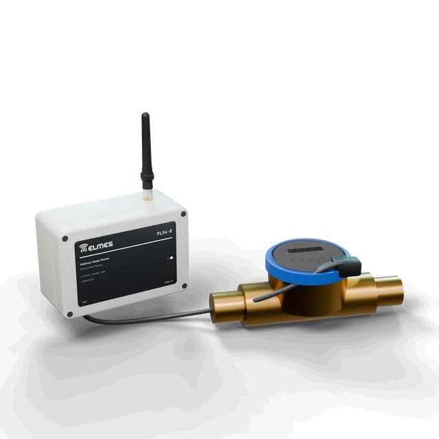
Wireless Meter Reading Node
Wireless pulse collection from water and electricity meters — years on a battery.
View details: Wireless Meter Reading Node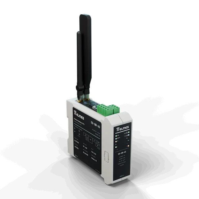 Coming soonModules, Boards & Gateways
Wireless Gateway / RTU
Connect every LoRa node in the field to SCADA, the cloud and PLCs with a single box.
View details: Wireless Gateway / RTU Coming soonAutomation & Telemetry
Telemetry & Process Intelligence
Field data into semantic memory, semantic memory into decisions.
Early access / pilot
View details: Telemetry & Process Intelligence